One of my biggest projects to date is a legged landing gear that allows helicopters to land on uneven terrain with large touchdown velocity. For a quick overview, please see the following video.
Inspiration
Traditional helicopter landing gears generally consist of two tubular skids, or three wheels for larger helicopters. These designs require a very flat landing surface and a gentle touchdown. For rescue or military situations, these ideal conditions might not always exist—for example, a helicopter might have to land quickly on sloped terrain to dispatch troops while being buffeted by wind.
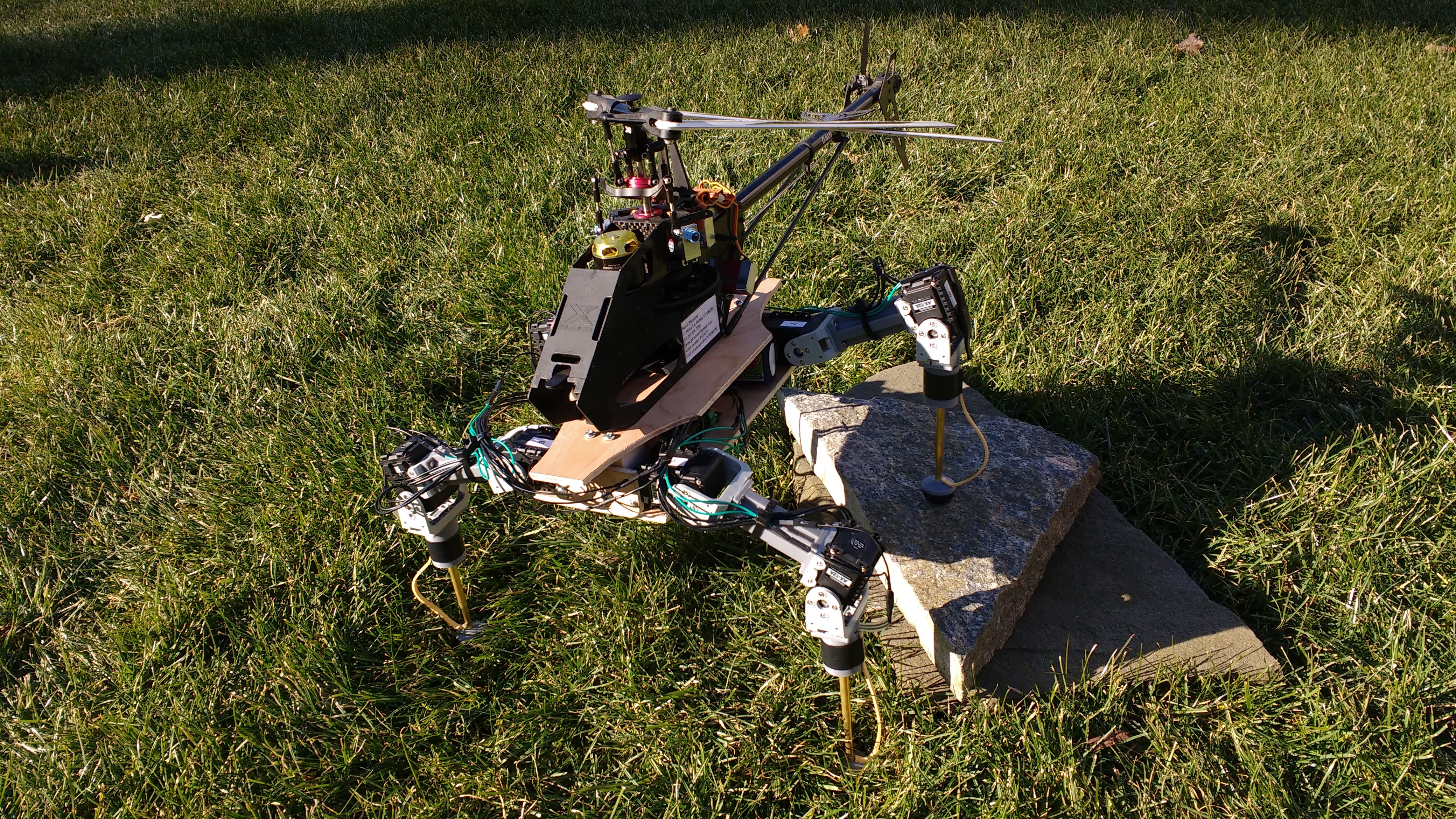
Enter Georgia Tech’s legged landing gear, which features four retractable legs that use force sensors in each foot to adapt to uneven terrain. As can be seen in the following image, the new gear can handle very uneven terrain. However, there did seem to be some possible areas of improvement.
In the video demonstration, the helicopter was shown being lowered very gently and precisely. This is most likely due to a mechanical limitation of the gear: its inability to absorb landing shock. Each leg consists of two motors and two completely rigid links. Correspondingly, if the helicopter hits the ground with any considerable velocity, the landing force will be transmitted instantaneously without giving the legs any time to retract. This would apply a torque to helicopter body, probably causing a crash.
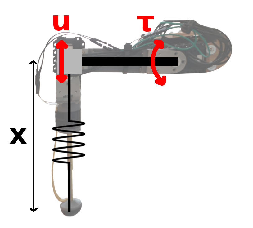
My improvement over the Georgia Tech design consists of adding a spring in the shank of each leg, absorbing the immediate shock and giving the motors enough time to react. As you will see in the following sections, this introduced numerous mechanical complexities and presented some interesting control problems.
Designing the Leg
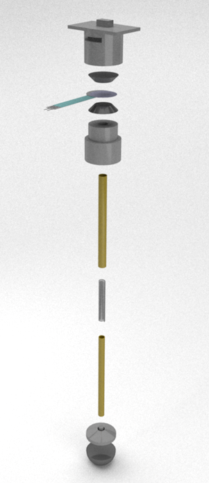
My first idea for the leg consisted of manufacturing my own series elastic actuators from 3D printed parts, using the design described here. After many iterations, it became clear that plastic, 3D printed parts had too much friction and imprecision to make this work. I then moved to including a spring in the shank of each leg, with force transmitted from the foot to the sensor through sliding brass tubes.

The leads of the force sensor were threaded through a slit in the housing. Two rubber frustums on each side of the sensor concentrated force on the sensor’s center, providing more reliable readings. I used hot glue to mate the two halves of the housing and the upper brass tube, and epoxy to connect the lower tube and the plastic foot. Finally, I lubricated the tubes and attached a rubber band between the housing and the foot to hold the shank together.
The thigh of the leg was comparatively simple. The knobs and screw holes on each end line up with the F2 and F3 brackets for the two Dynamixel AX-12As.
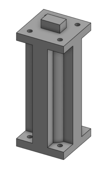
All plastic parts were printed using a Lulzbot Mini and HIPS filament on high resolution. One thing I had to watch out for during assembly was that the zero position of the Dynamixel (indicated by the notch in the servo horn) was aligned in the direction of the attached limb.
Force sensor
To read the resistance from each force sensor, I used voltage dividers with 1.7 kΩ resistors.  is connected to the analog in pin on the Arbotix-M. To figure out the force in newtons, I took a few data points with known weights and fit a regression.
Sliding Mode Control
Once the mechanical design of the leg was finished, I started looking into different control strategies for cushioning landing impact. One that stood out to me in particular was Sliding Mode Control (SMC).
There’s already a lot of good resources discussing sliding mode control so I’ll just touch on some of the more important points here. Let’s say we have a dynamical system of the form:
(1) 
Where  is a control input and
  is the state. We then identify a sliding surface
  , where
  is called a switching function and represents the “distance” from a certain state to the sliding surface. The sliding surface is designed to achieve some arbitrary task objectives. For example, we might constrain the end effector of a four-bar linkage to move along a line; all states resulting in the end effector lying on the line would have , and all states off the line would have
  Finally, we pick a discontinuous control law that drives the state trajectory to the sliding surface.
Control laws are classified according to how many time derivatives of  they drive to zero. If the controller can enforce
  , it’s a first order controller, and usually appears explicitly in the first time derivative of (relative degree one). If the controller can enforce
  , it’s a second order controller, and usually appears explicitly in the second time derivative of (relative degree two). I say usually because there are some exceptions to the relative degree rule—namely, the super twisting SMC, which I’ll be using later.
To understand this, let’s look at a mass sliding along a single axis. We’ll say the state of the system can be described by a single variable, the position . We want to drive the mass to a certain position  , so our switching surface would be:
(2) 
The core SMC controller would essentially be a bang-bang controller, where  and:
and:
(3) 
This is a first order sliding mode, since differentiating equation  and plugging in gives
  , indicating a relative degree of one. Theoretically this controller should drive the position to in finite time and maintain it in on that sliding mode perfectly; however, in practical implementations this kind of control strategy results in a phenomenon called chattering where the control input switches very quickly across the surface. This can cause actuator wear and is generally undesirable.
You may be asking yourself why the above controller would not be considered second order, since  could clearly be made zero simply by zeroing . This is because of the chattering problem described above; in reality, wouldn’t be enforceable with this control scheme since would actually fluctuate rapidly between +1 and -1, resulting in
  .
.
The crux of sliding mode control is picking a control law that quickly drives the state to the sliding surface while avoiding chattering. Many different controllers have been developed to solve this problem, and research is still ongoing in the field. One effective solution that I’ll focus on here is using a high-order sliding mode (HOSM) controller, which can enforce (at least) .
The HOSM controller I used is the super-twisting sliding mode controller. It’s somewhat unique in that it’s second order (can enforce ) but only has relative degree one ( appears explicitly in ). Here are the equations for the super-twisting controller:
(4) 
One-Leg Landing Controller
I started testing various simple controllers by dropping one leg with varying heights/springs and examining ground reaction force graphs. My first controller just retracted the leg with full speed starting the instant it read a non-zero ground force (shown right).
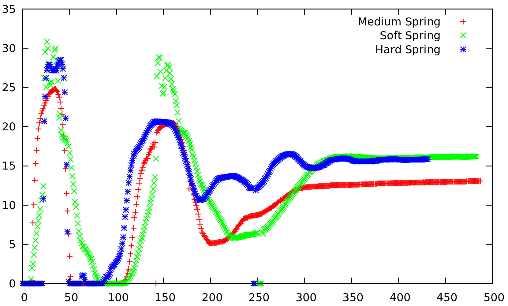
First let me apologize for the terrible graph; I originally wasn’t planning on doing a write-up and this was just some old testing data I found lying around. What’s important to notice though are the two humps in the graph, connected by a region of zero force. This meant that after an initial compression phase the leg retracted so quickly that it temporarily lifted off the ground before hitting ground a second time.
Therefore, I approached this sliding mode control problem by picking the very simple sliding surface:
(5) 
Where is the length of the shank. In words, the controller tried to keep the compression of the spring constant and avoid force fluctuations. I assumed the control input to be the second derivative of shank length (in reality I controlled hip torque  , but via linearization around the horizontal this can be approximated as a vertical acceleration at the knee).
Then I applied equation 4, using 80 for  and 20 for
  (hand tuned). This eliminated the earlier double-hump force profile, leaving just small hump after touchdown that drops down to a constant value. Unfortunately I can’t find a graph of the force profile with the super twisting algorithm though.
Overall Control Scheme
The sliding mode controller was just one component of the control scheme for the full four-leg landing gear. The overall control flow is outlined below:
- When all four legs are in the air (force sensors read zero), landing gear goes to the neutral position to prepare for landing
- Hip joints at 0.35 radians below horizontal, knee joints positioned to make shanks vertical
- When one leg senses contact with its force sensor, two things happen:
- The leg touching the ground enters “cushioning” mode (see below)
- Opposite leg extends to prevent the landing gear from toppling over
- If no further force is detected for two seconds, both the contact leg and the opposite leg return to the neutral position
- Cushion mode
- Specifically, employs the super-twisting sliding mode controller to eliminate chattering
- Tries to prevent force fluctuations and enforce a smooth deceleration
- Knee joint position determined by solving inverse kinematics on hip position and desired foot position
- Entered by a specific leg upon touching the ground
- Uses sliding mode control to track the constant-force manifold
- When all four legs are on the ground and the time derivatives of all the leg forces are reasonably small, “freeze” the actuators in place
- 0.5 seconds after takeoff (all four force sensors read zero) return legs to the neutral position
Putting it All Together
Components & Specifications
The gear ended up weight 1.2 kilograms, with a maximum leg length of 31 centimeters. I attached the gear to a Gaui X3, which weighed about 1 kilogram.
Here’s a list of all the materials I used in this project:
- Gaui X3 helicopter (I assembled this from a kit) and an appropriate transmitter
- Eight Dynamixel AX-12A servos and corresponding brackets/nuts/bolts
- Four Century Spring Corporation 155-B springs (5 lbs / in)
- Turnigy nano-tech 1300mAh 3S 45-90C Lipo battery
- Four Pololu 0.5 inch force sensing flexible resistors
- Arbotix-M microcontroller (Arduino)
- Three sets of Albion Alloys slide fit brass tubes (4mm, 5mm, 6mm diameter)
- Four 1” Hemisphere Rubber Bumpers (Sorbothane)
- Plywood, velcro, superglue, wood screws, small washers
- Solidworks 2016
- Lulzbot Mini (3D printer)
Leave a Reply